Copper-to-Aluminum Joint Integrity
HVAC manufacturers evaluating the use of aluminum components need to consider the best method for joining parts-such as evaporator and condenser coils-to secondary copper lines or assemblies. Several joining methods can be used, including: adhesives, mechanical joining, ultrasonic joining, soldering, and brazing.
When brazing or soldering, several parameters must be controlled to ensure proper joint integrity:
- Joint design (joint gap, shear depth, and Cu-to-Al orientation)
- Brazing or soldering consumables (alloy and flux)
Industry standards are not currently available, and recommendations vary. To assist manufacturers with this issue, Lucas-Milhaupt has performed tests investigating the effect different joint designs and types of brazing/soldering consumables have on the overall quality of copper-to-aluminum transition joints.
Test Process
A series of specimens with varying joints clearances were torch-brazed/soldered using Al/Si and Zn/Al alloys with non-corrosive fluxes. Specimens were then mechanically and pressure tested to determine the resulting joint quality. Metallurgical examination was performed to characterize the braze/solder quality for each family of joints.
Table 1 shows the alloy/flux combinations in flux-core form that were evaluated during this study.
Table 1. Common Alloys Used for Joining Cu to Al
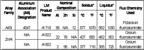
Copper-to-aluminum transition joints are often used to connect all-aluminum components to auxiliary copper lines. Due to operating pressures up to 35 bar (500 psi), strong leak-tight joints are the primary consideration when selecting the joint design, joining method, and consumables. For the alloys shown in Table 1, tensile, shear, and pressure tests were performed for braze/solder joints with different joint clearances.
Joint Clearances and Resulting Strength
Two separate strength tests were performed to evaluate the impact of alloy selection and joint clearances on the resulting copper-to-aluminum joint strength:
1. The first test utilized AWS C3.2 Standard as a guideline for evaluating braze/solder joint strength. The assemblies were heated by an oxygen-acetylene flame until both base metals were at brazing temperature, and then the braze/solder alloy was applied to the joint interface.
After the assemblies were brazed and prepared for testing, four pull specimens for each set of joint clearances and consumable used were tested in tension. Break-load values for each set of specimen were recorded and used to calculate the resulting shear stress in the filler metal. Data was compiled for joint clearances of 0 mm (0.000 in.), 0.08mm (0.003 in.), and 0.15mm (0.006 in.). Averages of the shear-stress values obtained for all sets of specimens tested are shown in Figure 1.
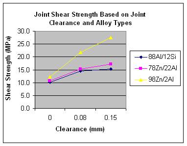
Figure 1. Avg.Shear Strength Based on Alloy Type and Joint Thickness
The results show that the highest shear strength was achieved with the 98Zn/2Al alloy for each of the three joint clearances tested. The difference in the strength seen between this alloy and the higher-aluminum-content alloys may be attributed to the potential for brittle intermetallic formation between higher-aluminum-containing braze alloys and the copper base material as indicated by Berlanga-Labari et al. Among the joint clearances tested, the 0.08mm and 0.15mm yielded the most consistent joint quality and strength. Little-to-no joint clearance led to excess flux voids and limited alloy fill, which in turn lowered the joint's integrity and strength.
2. The second strength test evaluated tube-to-tube brazed/soldered assemblies joined with different alloy-and joint-clearance combinations. This test was thought to be more representative of what is seen in industry for copper-to-aluminum transition joints. Joint clearances of 0.08 mm (0.003 in.) or 0.15 mm (0.006 in.) were chosen as a result of the shear strength test above. The assemblies were heated by a natural gas/oxygen flame until both base metals were at brazing temperature, and then the braze/solder alloy was applied to the joint interface.
After joining, four tube-to-tube specimens for each set of joint clearances and consumable were tested in tension by a universal 60K load tensile tester. The brazed/soldered assemblies were pulled until failure. Failure for all sets of specimens occurred in the aluminum-base-metal specimens. Although always in the aluminum-base material, the location of failure did vary dependent upon the type of alloy used for joining. All specimens soldered with the 98Zn/2Al alloy failed approximately 12-25mm (0.5-1 in.) above the joint, while specimens brazed with the 88Al/12Si alloy failed in the aluminum immediately above the braze joint. The difference in failure location is likely due to the higher temperature and increased alloy interaction (erosion) seen with the 88Al/12Si alloy. Specimens joined with the 78Zn/22Al alloy exhibited a mixture of aluminum-base-material failure above the braze joint and immediately adjacent to the braze.
Break-load values for each set were recorded and used to calculate the resulting tensile stress in the aluminum base metal at failure. Data was compiled for joint clearances of 0.08mm (0.003 in.), and 0.15mm (0.006 in.). Averages of the tensile stress values obtained for all sets of specimens tested are shown in and plotted in Figure 2.
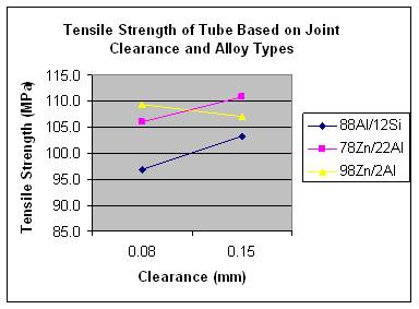
The results show that the highest assembly tensile strength for 0.08 mm clearance was achieved with the 98Zn/2Al alloy, while the highest tensile strength for 0.15mm clearance was obtained with the 78Zn/22Al alloy.
Joint Clearances and Pressure Resistance
HVAC components are often closed systems requiring hermetic, leak-tight joints. This is the case with aluminum-to-copper transition joints, which are commonly used to connect evaporator and condenser coils to copper liquid and suction lines. Operating pressures for these systems vary depending upon the type of refrigerant used, but typically range from 20-35 bar (290-500 psi). With this range in mind, a series of specimens were prepared, proof tested, and pressurized until failure. The tubular specimens prepared and joined were the same base materials and dimensions as used for the tube-assembly tensile tests.
Table 2. Summary of Pressure Test Results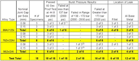
Note 1: Test specimen failed in the joint fillet at 131 bar (1900 psi)
Note 2: Test specimen failed in the joint fillet at 138 bar (2000 psi)
Note 3: Test Specimen failed in the aluminum base metal at 164 bar (2384 psi)
As seen in Table 2, burst pressures exceeding 173 bar (2500 psi) were realized in the majority of the brazed/soldered assemblies tested. Failures at these pressures occurred in both the aluminum base metal and the joint fillet for assemblies joined with the 88Al/12Si and 98Zn/2Al alloys, whereas assemblies brazed with the 78Zn/22Al alloy only failed in the aluminum parent material. Many manufacturers consider 138-173 bar (2000-2500 psi) burst pressure the acceptable minimum for failure in all-aluminum components. All transition joints tested during this study, except one, met or exceeded this range. The one specimen that failed below 173 bar (2000 psi) was joined with 88Al/12Si at a nominal clearance of 0.006 in. per side.
Joint Quality Comparison
Sections of the brazed/soldered shear and tensile specimens were retained and prepared for metallurgical examination to observe joint quality for the different alloy-and-joint configurations.
Overall joint quality was most consistent for the joints soldered with 98Zn/2Al. These joints exhibited the least amount of porosity, along with limited filler/base metal interaction. Complete joint penetration was observed with the 98Zn/2Al, with some gas porosity observed. All joint clearances brazed with the 78Zn/22Al alloy exhibited significant spherical and irregular porosity, which is typically indicative of gas or flux entrapment and shrinkage voids, respectively. The combination of these two voids can increase the likelihood of a leak path being exposed during pressure service.
Braze joints made with the 88Al/12Si alloy during these tests exhibited only spherical porosity, which was most commonly found at the copper/filler interface. This test group also displayed the most filler/base metal interaction or erosion among the test group. This interaction is increased when excessive braze temperatures are employed, which can often be seen with this alloy's higher liquidus temperature. Although leak tightness with this alloy may still be sound, base metal integrity/strength may be compromised due to this erosion.
As observed in the shear test specimens, similar joint features of alloy interaction, gas porosity, and shrinkage voids were also seen in the solder/brazed tube-to-tube assemblies. In general, not maintaining consistent joint clearances per side caused inconsistencies in the amount of alloy pull-through and base metal interaction.
Conclusions
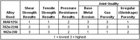
Based on the data and the visual observations discussed above, Table 3 provides a qualitative rating of the copper-to-aluminum transition joints produced with the three different filler metals tested.
Table 3. Qualitative Rating of Alloy Systems Tested
We trust that this research is helpful to you in evaluating joint designs and brazing/soldering consumables when joining copper to aluminum for HVAC components.
Questions? Lucas-Milhaupt's brazing experts can help you navigate the challenges of joining aluminum. For more information on aluminum brazing, aluminum-to-copper brazing, HVAC coil brazing, and related processes, please contact us. For information on Lucas-Milhaupt's Handy One® aluminum brazing and soldering products, click here.
______