Radiographic Examination - Discontinuity Images on Film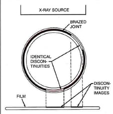 Examining finished joints may be the final step in the brazing process, but inspection procedures should be incorporated into the design stage. Your methodology will depend on the application, service and end-user requirements plus regulatory codes and standards.
Define your acceptance criteria for any discontinuity with considerations for shape, orientation, location (surface or subsurface) and relationship to other discontinuities. Be sure to state acceptance limits in terms of minimum requirements.
Discontinuities
Common discontinuities of brazed joints, identified through nondestructive examination, include:
- Voids or porosity - an incomplete flow of brazing filler metal which can decrease joint strength and allow leakage-often caused by improper cleaning, incorrect joint clearance, insufficient filler metal, entrapped gas or thermal expansion.
- Flux entrapment - resulting from insufficient vents in the joint design-preventing the flow of filler metal and reducing joint strength as well as service life
- Discontinuous fillets - areas on the joint surface where the fillet is interrupted-usually discovered by visual inspection
- Base metal erosion (or alloying) - when the filler metal alloys with the base metal during brazing-movement of the alloy away from the fillet may cause erosion and reduce joint strength
- Unsatisfactory surface condition or appearance - excessive filler metal or rough surfaces-may act as corrosion sites and stress concentrators, also interfering with further testing
- Cracks - reducing strength and service life of the joint-may also be caused by liquid metal embrittlement.
Examination Methods
Nondestructive testing methods of checking quality and specification conformance include:
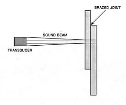
Typical Immersion Ultrasonic Setup
- Visual examination - with or without magnification-for evaluating voids, porosity, surface cracks, fillet size and shape, discontinuous fillets plus base metal erosion (not internal issues such as porosity and lack of fill)
- Leak testing - for determining gas- or liquid-tightness of a brazement. Pressure (or bubble leak) testing involves the application of air at greater-than-service pressures. Vacuum testing is useful for refrigeration equipment and detection of minute leaks, employing a mass spectrometer and a helium atmosphere.
- Proof testing - subjecting a brazed joint to a one-time load greater than the service level-applied by hydrostatic methods, tensile loading or spin testing
- Radiographic examination - useful in detecting internal flaws, large cracks and braze voids, if thickness and X-ray absorption ratios permit delineation of the brazing filler metal-cannot verify a proper metallurgical bond
- Ultrasonic examination - a comparative method for evaluating joint quality, in immersion mode or contract mode-involves reflection of sound waves by surfaces, using a transducer to emit a pulse and receive echoes
- Liquid penetrant examination - dye and fluorescent penetrants may detect cracks open to the surface of joints-not suitable for inspection of fillets, where some porosity is always present
- Acoustic emission testing - evaluating the extent of discontinuity-using the premise that acoustic signals undergo a frequency or amplitude change when traveling across discontinuities
- Thermal transfer examination - detects changes in thermal transfer rates due to discontinuities or unbrazed areas-images show brazed areas as light spots and void areas as dark spots
There are also several destructive and mechanical testing methods, often used in random or lot testing:
- Peel testing - useful for evaluating lap joints and production quality control for general quality of the bond plus presence of voids and flux inclusions-where one member is held rigid while the other is peeled away from the joint
- Metallographic examination-testing the general quality of joints-detecting porosity, poor filler metal flow, base metal erosion and improper fit
- Tension and shear testing - determines strength of a joint in tension or in shear-used during qualification or development rather than production
- Fatigue testing - testing the base metal plus the brazed joint-a time-consuming and costly method
- Impact testing - determines the basic properties of brazed joints-generally used in a lab setting
- Torsion testing - used on brazed joints in production quality control-for example, studs or screws brazed to thick sections
The size, complexity and severity of the application determine the best inspection method, and several methods may be required. If you are unable to develop an accurate and dependable method of inspecting a critical brazed joint, consider revisiting your joint design to allow adequate inspection.
Source: AWS Brazing Handbook
CONCLUSION:
Examining finished joints may be the final step in the brazing process, but inspection procedures should be incorporated into the design stage. Both nondestructive and destructive methods may be employed, depending on the application, service and end-user requirements plus regulatory codes and standards.
Lucas-Milhaupt is dedicated to providing expert information for Better Brazing. Please feel free to share this blog posting with associates. For further information, see Lucas-Milhaupt's series of brazing videos, consider our seminars and on-site training, and contact us if we may be of assistance.
